HC3-9
Data:
HC3-9 versions: 15 different intensification factors
PIN: 20–207 bar
PH: 800 bar maximum
PRETURN: As low as possible (return pressure to tank)
POUTLET: PH = (PIN – PRETURN) x intensification factor
Mounting: Cartridge
Weight: 1.3 kg.
Description
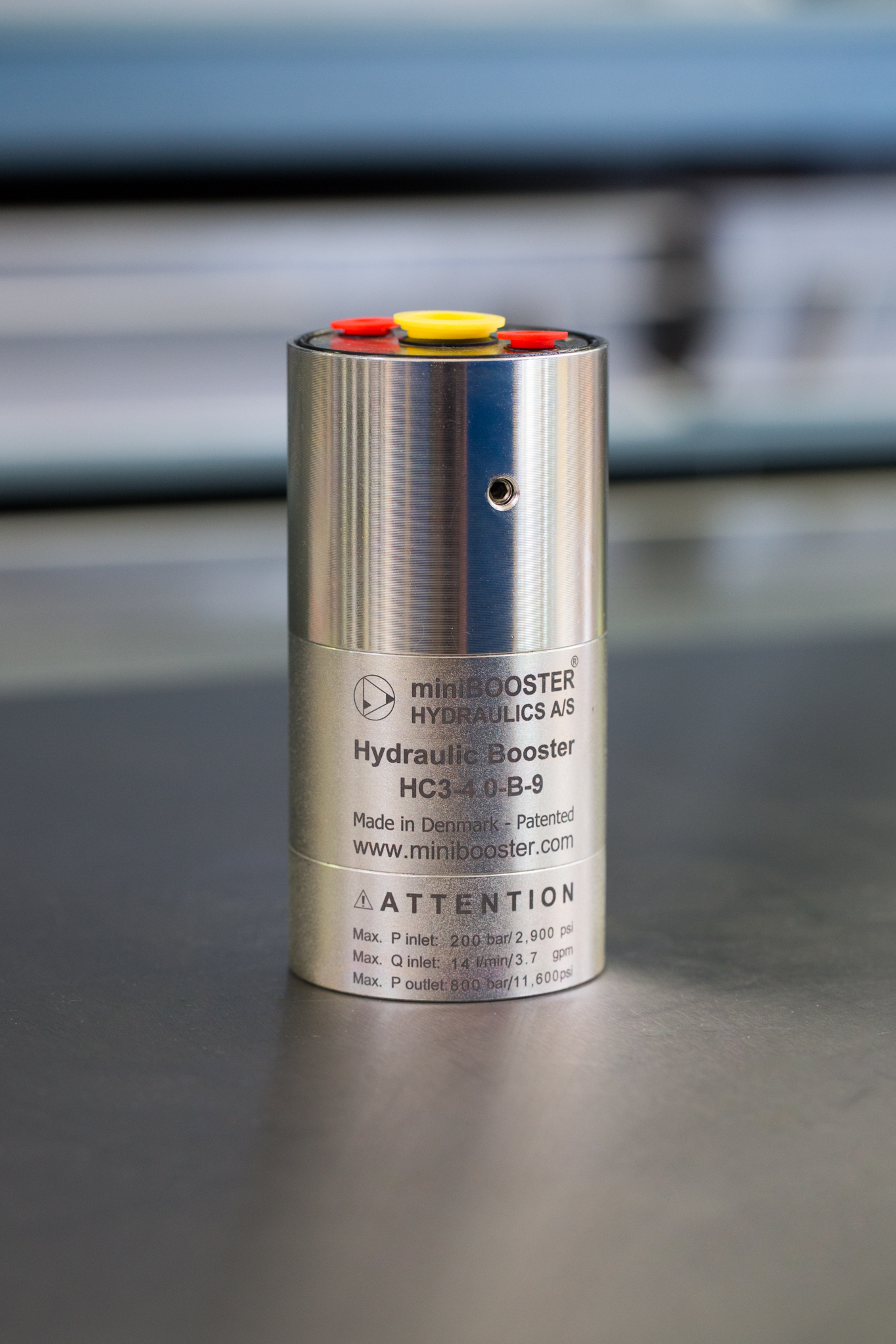
HC3-9 is a compact hydraulic cartridge miniBOOSTER unit weighing only 1.3 kg. It is ideal for use in applications where it is desirable to mount the unit on or in a manifold, cylinder, or other device.
The HC3-9 raises supplied pressure to a higher outlet pressure and automatically compensates for consumption of oil to maintain the high pressure. Adjustment of the outlet pressure is carried out by varying the supplied pressure.
Flow rates
| Intensification factor i | Max. intensified outlet flow l/min | Max. inlet flow l/min |
|---|---|---|
| 1.2 | 3.5 | 8.0 |
| 1.5 | 4.2 | 12.0 |
| 2.0 | 3.2 | 12.0 |
| 2.2 | 2.9 | 12.0 |
| 2.5 | 2.7 | 13.0 |
| 2.8 | 2.5 | 13.0 |
| 3.2 | 2.5 | 15.0 |
| 4.0 | 2.0 | 14.0 |
| 5.0 | 1.6 | 14.0 |
| 6.6 | 1.3 | 13.0 |
| 9.0 | 0.9 | 13.0 |
| 13.0 | 0.6 | 12.0 |
| 16.0 | 0.5 | 12.0 |
| 20.0 | 0.3 | 12.0 |
| 25.0 | 0.2 | 12.0 |
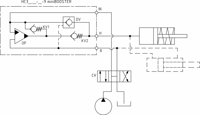
Functions
The basic operation is illustrated in the function diagram. The oil is fed through the connecting plate to the control valve to the IN port of the HC3 flowing freely through check valves KV1, KV2 and DV to the high pressure side H.
From the high pressure side H oil is fed to port A on the connecting plate. In this condition maximum flow through the booster is achieved giving a fast forward function. When pump pressure is reached on the high pressure side H, valves KV1, KV2 and DV will close. The end pressure will be achieved by the oscillating pump unit OP. The unit will automatically stall when end pressure on high pressure side is reached. If there is a pressure drop on the high pressure side due to consumption or leakage, the OP valve will automatically operate to maintain the end pressure.
Function diagram
3-146-00
Dimensions
Dimension drawing 3-203-01
Fluids and materials
Additional information is available on the website under Products → General specifications.
Ordering an HC3-9
Ordering example of an HC3-9 with i = 4.0 DV incorporated: HC3 – 4.0 – B – 9
Attention note!
The G-model is available in 2 variants, when ordering please specify accordingly:
- Dynamic – low hysteresis: Ordering example of an HC3-9 with i = 4.0 RV incorporated: HC3 – 4.0 – G – 9
- Fail safe – high hysteresis: The RV valve opening ratio is to be determined on individual basis. Contact our technical support. Ordering example of an HC3-9 with i = 4.0 RV with opening ratio x.x incorporated: HC3 – 4.0 – G – x.x – 9
Model
- HC3
Intensification, i
- Select factor
- See flow rate table
Model version
- Select type
- A = without DV
- B = with DV
- G = with proportional valve
Connections
- 9
Mounting:
3-204-01 Mounting instruction
miniBOOSTER Hydraulics A/S
Fynsgade 3
DK - 6400 Sønderborg
Tel: +4574429292
Fax: +4574424204
info@minibooster.com
Monday-Friday: 8AM -5PM
(GMT +1)

We will be closed for the following public holidays in May and June:
Thursday, 9th May – Ascension Day
Monday, 20th May – Whit Monday
Wednesday 5th June – Constitution Day
Inquiries and orders will be processed on the next business day.