HC7
Data:
HC7 versions: 10 different intensification factors
PIN: 20 – 207 bar
PH: 2,000 bar maximum
PRETURN: As low as possible (return pressure to tank)
POUTLET: PH = (PIN – PRETURN) x intensification factor
Mounting: Inline tube
Weight: 1.5 kg.
Description
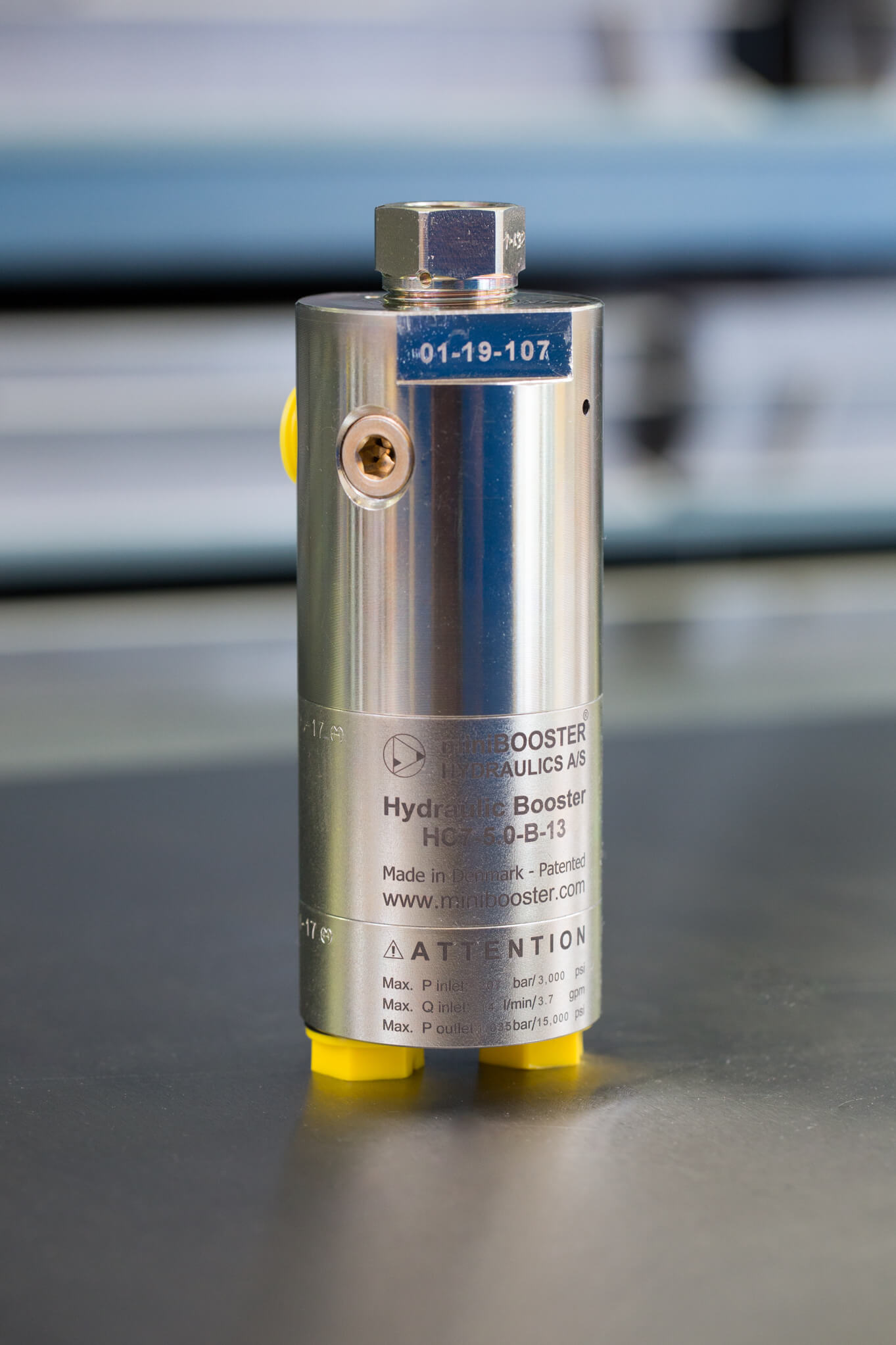
The HC7 is a very compact high-pressure unit capable of delivering pressure up to 2,000 bar weighing only 1.5 kg. It is ideal for use in portable applications like on power packs.
The HC7 raises supplied pressure to a higher outlet pressure and automatically compensates for consumption of oil to maintain the high pressure. Adjustment of the outlet pressure is carried out by varying the supplied pressure. With the choice of different high- pressure adapters, a variety of threads can be obtained from the M22x1.5 thread in the HP port. Higher pressure is available on request.
Flow rates
| Intensification factor i | Max. intensified outlet flow l/min | Max. inlet flow l/min |
|---|---|---|
| 4.0 | 2.0 | 14.0 |
| 5.0 | 1.6 | 14.0 |
| 6.6 | 1.3 | 13.0 |
| 7.6 | 1.1 | 13.0 |
| 9.0 | 0.9 | 13.0 |
| 10.3 | 0.8 | 12.0 |
| 13.0 | 0.6 | 12.0 |
| 16.0 | 0.5 | 12.0 |
| 20.0 | 0.3 | 12.0 |
| 25.0 | 0.2 | 12.0 |
Functions
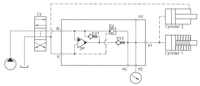
The basic operation is illustrated in the function diagram. Oil is fed through the directional valve CV to the IN port, flowing freely through the check valves KV1, KV2 and DV to the high-pressure side H. In this condition maximum flow through the booster is achieved, giving a fast-forward function.
When pump pressure is reached on the high-pressure side H, valves KV1, KV2 and DV will close. The end pressure will be achieved by the oscillating pump unit OP. The unit will automatically stall when end pressure on the high-pressure side H is reached. If a pressure drop on the high-pressure side exists due to consumption or leakage, the OP valve will automatically operate to maintain the end pressure.
Function diagram
7-105-02
Dimensions
Dimension drawing 7-120-12
Connection types
| Connection | IN / R | H |
|---|---|---|
| 1 | 1/4" BSPP | M22 x 1.5 |
| 2 | 7/16-20" UNF | M22 x 1.5 |
High-pressure adapters
High-pressure adapter ordering codes and specifications are shown in the PDF-file: 7-900-11
Fluids and materials
Additional information is available on the website under Products → General specifications.
Ordering an HC7
Ordering example of an HC7 with i = 13.0, H1 M22 x 1.5 and H2 9/16-18 UNF, DV incorporated and BSPP connections: HC7 – 13.0 – B – 12
Attention notes!
High-pressure adapter is required, please specify ordering code – see high-pressure adapter table.
High-pressure adapters will be factory mounted.
The G-model is available in 2 variants, when ordering please specify accordingly:
- Dynamic – low hysteresis: Ordering example of an HC7 with i = 13.0 RV incorporated, H1 M22 x 1.5 and H2 9/16-18 UNF and BSPP connections: HC7 – 13.0 – G – 12
- Fail safe – high hysteresis: The RV valve opening ratio is to be determined on individual basis. Contact our technical support. Ordering example of an HC7 with i = 13.0 RV with opening ratio x.x incorporated, H1 M22 x 1.5 and H2 9/16-18 UNF and BSPP connections: HC7 – 13.0 – G – x.x – 12
Model
- HC7
Intensification, i
- Select factor
- See flow rate table
Model version
- Select type
- A = without DV
- B = with DV
- G = with proportional valve
Connections
- Select thread
- See table below
| Ordering code | IN / R | H1 | H2 | H3 | H4 |
|---|---|---|---|---|---|
| HC7-___-__-11 | 1/4" BSPP | M22 x 1.5 | - | - | - |
| HC7-___-__-21 | 7/16-20 UNF | M22 x 1.5 | - | - | - |
| HC7-___-__-12 | 1/4" BSPP | M22 x 1.5 | 9/16-18 UNF | - | - |
| HC7-___-__-22 | 7/16-20 UNF | M22 x 1.5 | 9/16-18 UNF | - | - |
| HC7-___-__-13 | 1/4" BSPP | M22 x 1.5 | 9/16-18 UNF | 9/16-18 UNF | - |
| HC7-___-__-23 | 7/16-20 UNF | M22 x 1.5 | 9/16-18 UNF | 9/16-18 UNF | - |
| HC7-___-__-14 | 1/4" BSPP | M22 x 1.5 | 9/16-18 UNF | 9/16-18 UNF | 9/16-18 UNF |
| HC7-___-__-24 | 7/16-20 UNF | M22 x 1.5 | 9/16-18 UNF | 9/16-18 UNF | 9/16-18 UNF |
Max. tightening torque BSPP
| IN / R | |
|---|---|
| 1/4" BSPP | |
| with steel washer | 4.0 da/Nm |
| with cutting edge | 4.0 da/Nm |
Max. tightening torque UNF
| IN / R | |
|---|---|
| 7/16-20" UNF | |
| with o-ring | 2.0 da/Nm |
miniBOOSTER Hydraulics A/S
Fynsgade 3
DK - 6400 Sønderborg
Tel: +4574429292
Fax: +4574424204
info@minibooster.com
Monday-Friday: 8AM -5PM
(GMT +1)

We will be closed for the following public holidays in May and June:
Thursday, 9th May – Ascension Day
Monday, 20th May – Whit Monday
Wednesday 5th June – Constitution Day
Inquiries and orders will be processed on the next business day.